
Page 17 - Mechanical design of microresonators _ modeling and applications
P. 17
0-07-145538-8_CH01_16_08/30/05
Design at Resonance of Mechanical Microsystems
16 Chapter One
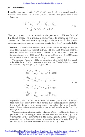
By collecting Eqs. (1.46), (1.47), (1.48), and (1.49), the overall quality
factor that is produced by both Couette- and Stokes-type flows is cal-
culated as
1 1 1 1 1
Q = Q + Q + Q + Q
C,u C,s S,a S,u
(1.52)
Ȧ
= {z + y + 1+ f (ȕ) į}
0
0
2
ʌȞ ȝ
The quality factor is calculated in the particular addition form of
Eq. (1.52) because it is inversely proportional to various energy loss
sources, and the total damping energy is the sum of all the partial
damping energies, such as the ones given in Eqs. (1.46) through (1.49).
Example: Compare the contributions of the four types of flows present in the
slide-film phenomenon pictured in Figs. 1.12 and 1.13. Consider that the
moving plate has the dimensions l = 200 ȝm, w = 50 ȝm, and t = 2 ȝm; and
3
its mass density is ȡ = 2300 kg/m . The spring stiffness is k = 3.125 N/m, and
the fluid is air with a dynamic viscosity ȝ = 0.0345 kg/ms.
The resonant frequency of the mass-spring system is 260,643 Hz, as cal-
culated by Eq. (1.5). Also, the parameter ȕ is 93,210. The following ratios can
be formulated by Eqs. (1.46) through (1.49):
1 Q z
/ C,u Q 0
= =
1 / Q Q z + y +[1+ f (ȕ)]į
C,u 0 0
1 Q y
/ C,s Q 0
= =
1 / Q Q z + y +[1+ f (ȕ)]į
C,s 0 0
(1.53)
1 Q
/ S,a Q į
= =
1 / Q Q z + y +[1+ f (ȕ)]į
S,a 0 0
1 Q
/ S,u Q į f (ȕ)
= =
1 / Q Q z + y +[1+ f (ȕ)]į
S,u 0 0
Equations (1.53) actually indicate that the overall quality factor is smaller
than each of its components, since adding more damping factors increases
the overall damping and consequently diminishes the overall quality
factor. These ratios depend on only z 0 and y 0 and are plotted in Figs. 1.14
through 1.17.
The smallest contribution to the reduction of the overall quality factor is
produced by the Stokes-type flow underneath the movable plate (Fig. 1.17),
whereas the largest contribution in the overall quality factor reduction is
generated by the Couette-type flow underneath the movable plate (Fig. 1.14)
and the Stokes-type flow above the movable plate (Fig. 1.16).
Downloaded from Digital Engineering Library @ McGraw-Hill (www.digitalengineeringlibrary.com)
Copyright © 2004 The McGraw-Hill Companies. All rights reserved.
Any use is subject to the Terms of Use as given at the website.