
Page 103 - Mechanical design of microresonators _ modeling and applications
P. 103
0-07-145538-8_CH02_102_08/30/05
Basic Members: Lumped- and Distributed-Parameter Modeling and Design
102 Chapter Two
(outlined previously in this distributed-parameter section) and can be
expressed as
2
Ȧ = 2 U max
2
ȡt ฒ w (x, y) dA (2.211)
A 0
where U max is the maximum potential energy and is formulated as
2
2
( ) ( ) ( )( )
2
2
2
2
w
w
w
w
0
0
0
0
+
+2ȝ
D x 2 y 2 x 2 y 2
U max = 2ฒ 2 2 dA (2.212)
w
0
A +2(1 íȝ) ( x y)
The flexural rigidity D is defined as
Et 3
D = (2.213)
2
12(1 íȝ )
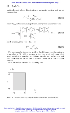
For a rectangular thin plate which is fixed (clamped on the contour),
as sketched in Fig. 2.39, a suitable w 0 function needs to be used, that
would satisfy the boundary conditions, namely, zero deflections and
zero slopes (partial derivatives of deflection in terms of x or y) on the
contour.
Such a function could be the following one:
y
l2
x
l1
Figure 2.39 Top view of rectangular plate with dimensions and reference frame.
Downloaded from Digital Engineering Library @ McGraw-Hill (www.digitalengineeringlibrary.com)
Copyright © 2004 The McGraw-Hill Companies. All rights reserved.
Any use is subject to the Terms of Use as given at the website.