
Page 309 - Mechanical design of microresonators _ modeling and applications
P. 309
0-07-145538-8_CH06_308_08/30/05
Microcantilever and Microbridge Systems for Mass Detection
308 Chapter Six
0.0
0.06
0.05
0.04
f m
0.03
0.02
0.01
0
0 0.1 0.2 0.3 0.4 0.5
c l
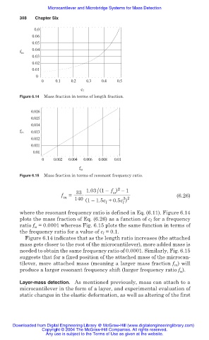
Figure 6.14 Mass fraction in terms of length fraction.
0.016
0.015
0.014
f m 0.013
0.012
0.011
0.01
0 0.002 0.004 0.006 0.008 0.01
f ω
Figure 6.15 Mass fraction in terms of resonant frequency ratio.
2
/
33 1.03 (1– f ) –1
Ȧ
f = (6.26)
m 140 3 2
(1– 1.5c +0.5c )
l l
where the resonant frequency ratio is defined in Eq. (6.11). Figure 6.14
plots the mass fraction of Eq. (6.26) as a function of c l for a frequency
ratio f = 0.0001 whereas Fig. 6.15 plots the same function in terms of
Ȧ
the frequency ratio for a value of c l = 0.1.
Figure 6.14 indicates that as the length ratio increases (the attached
mass gets closer to the root of the microcantilever), more added mass is
needed to obtain the same frequency ratio of 0.0001. Similarly, Fig. 6.15
suggests that for a fixed position of the attached mass of the microcan-
tilever, more attached mass (meaning a larger mass fraction f ) will
m
produce a larger resonant frequency shift (larger frequency ratio f Ȧ ).
Layer-mass detection. As mentioned previously, mass can attach to a
microcantilever in the form of a layer, and experimental evaluation of
static changes in the elastic deformation, as well as altering of the first
Downloaded from Digital Engineering Library @ McGraw-Hill (www.digitalengineeringlibrary.com)
Copyright © 2004 The McGraw-Hill Companies. All rights reserved.
Any use is subject to the Terms of Use as given at the website.