
Page 310 - Mechanical design of microresonators _ modeling and applications
P. 310
0-07-145538-8_CH06_309_08/30/05
Microcantilever and Microbridge Systems for Mass Detection
Microcantilever and Microbridge Systems for Mass Detection 309
z
deposited l p l 1
l p l 1
layer
F 2z
l s
q z F 1z M 1y
deflection sensing
microcantilever x 5 4 3 2 l s 1
l l
(a) (b)
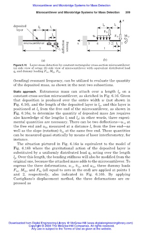
Figure 6.16 Layer-mass detection by constant rectangular cross-section microcantilever:
(a) side view of setup; (b) side view of microcantilever with equivalent distributed load
q z and dummy loading F 1z , M 1y , F 2z .
(bending) resonant frequency, can be utilized to evaluate the quantity
of the deposited mass, as shown in the next two subsections.
Static approach. Extraneous mass can attach over a length l p on a
constant-cross-section microcantilever, as sketched in Fig. 6.16. Given
that deposition is produced over the entire width w (not shown in
Fig. 6.16), and the length of the deposited layer is l p , and this layer is
positioned at l s from the free end of the microcantilever, as shown in
Fig. 6.16a, to determine the quantity of deposited mass ǻm requires
also knowledge of the lengths l l and l p ; in other words, three experi-
mental quantities are necessary. There can be two deflections—u 1z at
the free end and u 2z measured at a distance l s from the free end—as
well as the slope (rotation) ș 1y at the same free end. These quantities
can be measured quasi-statically by means of laser interferometry, for
instance.
The situation pictured in Fig. 6.16a is equivalent to the model of
Fig. 6.16b where the gravitational action of the deposited layer is
substituted by a uniformly distributed load q acting over the length
z
l p . Over this length, the bending stiffness will also be modified from the
original one, because the attached mass adds to the microcantilever. To
express the three deformations, u , ș , and u , three dummy loads
1z
1y
2z
F 1z , M 1y , and F 2z (all equal to zero in the end) are applied at points 1
and 2, respectively, also indicated in Fig. 6.16b. By applying
Castigliano’s displacement method, the three deformations are ex-
pressed as
Downloaded from Digital Engineering Library @ McGraw-Hill (www.digitalengineeringlibrary.com)
Copyright © 2004 The McGraw-Hill Companies. All rights reserved.
Any use is subject to the Terms of Use as given at the website.