
Page 315 - Mechanical design of microresonators _ modeling and applications
P. 315
0-07-145538-8_CH06_314_08/30/05
Microcantilever and Microbridge Systems for Mass Detection
314 Chapter Six
1.1
1
ω b,0 / ω b 1
0 0
c t
c lp 0.01
1 1
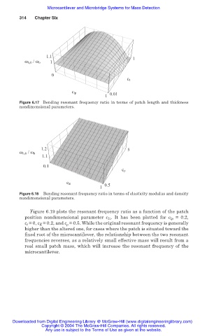
Figure 6.17 Bending resonant frequency ratio in terms of patch length and thickness
nondimensional parameters.
1.2 5
ω b,0 / ω b
1.1
0. 1
0.1
c ρ
c E 0.5
1 1
Figure 6.18 Bending resonant frequency ratio in terms of elasticity modulus and density
nondimensional parameters.
Figure 6.19 plots the resonant frequency ratio as a function of the patch
position nondimensional parameter c l1 . It has been plotted for c lp = 0.2,
c t = 0, c E = 0.2, and c ȡ = 0.5. While the original resonant frequency is generally
higher than the altered one, for cases where the patch is situated toward the
fixed root of the microcantilever, the relationship between the two resonant
frequencies reverses, as a relatively small effective mass will result from a
real small patch mass, which will increase the resonant frequency of the
microcantilever.
Downloaded from Digital Engineering Library @ McGraw-Hill (www.digitalengineeringlibrary.com)
Copyright © 2004 The McGraw-Hill Companies. All rights reserved.
Any use is subject to the Terms of Use as given at the website.