
Page 316 - Mechanical design of microresonators _ modeling and applications
P. 316
0-07-145538-8_CH06_315_08/30/05
Microcantilever and Microbridge Systems for Mass Detection
Microcantilever and Microbridge Systems for Mass Detection 315
1.03
1.02
1.01
1
ω b,0 / ω b
0.99
0.98
0.97
0 0.2 0.4 0.6 0.8
c l1
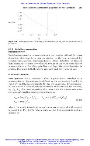
Figure 6.19 Bending resonant frequency ratio in terms of patch position nondimensional
parameter.
6.3.2 Variable-cross-section
microcantilevers
Variable-cross-section microcantilevers can also be utilized for mass
deposition detection in a manner similar to the one presented for
constant-cross-section microcantilevers. Mass detection is treated
here similarly to mass detection by means of constant-cross-section
microcantilevers; therefore pointlike and layerlike mass detection is
analyzed by using both the static approach and the resonant one.
Point-mass detection
Static approach. As a reminder, when a point mass attaches to a
microcantilever, its position (as defined by the parameters l x and l y in
Fig. 3.37) and the mass quantity ǻm are the unknowns. By experimen-
tal evaluation of three elastic deformations at the free tip, for instance,
u 1z , ș 1y , ș 1x , the three equations that were valid for a constant-cross-
section configuration can be reformulated as
u = ǻmg(C – l C ) ș = ǻmg(C – l C )
1z 2,l x 2,c 1y 2,c x 2,r
(6.43)
ș = ǻmgl C
1x y 2,t
where the newly introduced compliances are calculated with respect
to point 2 in Fig. 3.37a (which explains the first subscript) and are
defined as
Downloaded from Digital Engineering Library @ McGraw-Hill (www.digitalengineeringlibrary.com)
Copyright © 2004 The McGraw-Hill Companies. All rights reserved.
Any use is subject to the Terms of Use as given at the website.