
Page 50 - Mechanical design of microresonators _ modeling and applications
P. 50
0-07-145538-8_CH02_49_08/30/05
Basic Members: Lumped- and Distributed-Parameter Modeling and Design
Basic Members: Lumped- and Distributed-Parameter Modeling and Design 49
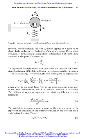
M y
eccentric
fixed shaft
u z
k c,y
Figure 2.6 Lumped-parameter cross-bending stiffness for a microcantilever.
theorem, which expresses the load L i that is applied at a point on an
elastic body as the partial derivative of the strain energy U evaluated
with respect to the corresponding elastic deformation d i about the load
direction at the point of interest, or
U
L = (2.3)
i
d
i
This approach is implemented with ease when the cross section is con-
stant, but is more difficult to utilize for variable-cross-section members.
The strain energy corresponding to axial loading can be expressed as
2
l F (x) l du (x) 2
1
x
a
2ฒ
U = 2Eฒ A(x) = E A(x) dx dx (2.4)
a
0 0
where F a (x) is the axial load, A(x) is the cross-sectional area, u x (x)
is the axial deformation, and E is Young’s modulus of elasticity.
The differential equation expressing the static equilibrium in axial
loading is
2
d u (x)A(x)
x
=0 (2.5)
dx 2
The axial deformation at a generic point on the micromember can be
expressed as a function of the axial deformation at the free end and a
distribution function f (x) as
a
u (x) = f (x)u (2.6)
x a x
Downloaded from Digital Engineering Library @ McGraw-Hill (www.digitalengineeringlibrary.com)
Copyright © 2004 The McGraw-Hill Companies. All rights reserved.
Any use is subject to the Terms of Use as given at the website.