
Page 49 - Mechanical design of microresonators _ modeling and applications
P. 49
0-07-145538-8_CH02_48_08/30/05
Basic Members: Lumped- and Distributed-Parameter Modeling and Design
48 Chapter Two
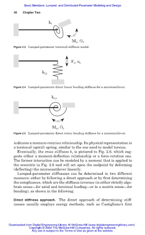
k t
M x , x
Figure 2.3 Lumped-parameter torsional stiffness model.
F z , u z
k l,y
Figure 2.4 Lumped-parameter direct linear bending stiffness for a microcantilever.
k r,y
M y , y
Figure 2.5 Lumped-parameter direct rotary bending stiffness for a microcantilever.
indicates a moment-rotation relationship. Its physical representation is
a torsional (spiral) spring, similar to the one used to model torsion.
Eventually, the cross stiffness k is pictured in Fig. 2.6, which sug-
c
gests either a moment-deflection relationship or a force-rotation one.
The former interaction can be modeled by a moment that is applied to
the eccentric in Fig. 2.6 and will act upon the endpoint by deforming
(deflecting) the microcantilever linearly.
Lumped-parameter stiffnesses can be determined in two different
manners: either by following a direct approach or by first determining
the compliances, which are the stiffness inverses (in either strictly alge-
braic sense–for axial and torsional loading–or in a matrix sense–for
bending), as shown in the following.
Direct stiffness approach. The direct approach of determining stiff-
nesses usually employs energy methods, such as Castigliano’s first
Downloaded from Digital Engineering Library @ McGraw-Hill (www.digitalengineeringlibrary.com)
Copyright © 2004 The McGraw-Hill Companies. All rights reserved.
Any use is subject to the Terms of Use as given at the website.