
Page 48 - Mechanical design of microresonators _ modeling and applications
P. 48
0-07-145538-8_CH02_47_08/30/05
Basic Members: Lumped- and Distributed-Parameter Modeling and Design
Basic Members: Lumped- and Distributed-Parameter Modeling and Design 47
k a
F x , u x
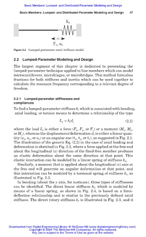
Figure 2.2 Lumped-parameter axial stiffness model.
2.2 Lumped-Parameter Modeling and Design
The largest segment of this chapter is dedicated to presenting the
lumped-parameter technique applied to line members which can model
microcantilevers, microhinges, or microbridges. This method furnishes
fractions for both stiffness and inertia which can be used together to
calculate the resonant frequency corresponding to a relevant degree of
freedom.
2.2.1 Lumped-parameter stiffnesses and
compliances
To find a lumped-parameter stiffness k which is associated with bending,
i
axial loading, or torsion means to determine a relationship of the type
L = k d (2.2)
i
i i
where the load L is either a force (F , F , or F ) or a moment (M , M ,
y
x
z
x
y
i
or M ), whereas the displacement/deformation d is either a linear quan-
z
i
tity (u , u , or u ) or an angular one (ș , ș , or ș ), as suggested in Fig. 2.1.
z
x
z
y
x
y
The illustration of the generic Eq. (2.2) in the case of axial loading and
deformation is sketched in Fig. 2.2, where a force applied at the free end
about the longitudinal (x) direction of the fixed-free member produces
an elastic deformation about the same direction at that point. This
elastic interaction can be modeled by a linear spring of stiffness k .
a
Similarly, a moment that is applied about the longitudinal (x) axis at
the free end will generate an angular deformation at that point, and
this interaction can be modeled by a torsional spring of stiffness k , as
t
illustrated in Fig. 2.3.
In bending (about the y axis, for instance), three types of stiffnesses
can be identified. The direct linear stiffness k , which is modeled by
l
means of a linear spring, as shown in Fig. 2.4, is based on a force-
deflection relationship and is similar to the previously defined axial
stiffness. The direct rotary stiffness k is illustrated in Fig. 2.5, and it
r
Downloaded from Digital Engineering Library @ McGraw-Hill (www.digitalengineeringlibrary.com)
Copyright © 2004 The McGraw-Hill Companies. All rights reserved.
Any use is subject to the Terms of Use as given at the website.