
Page 47 - Mechanical design of microresonators _ modeling and applications
P. 47
0-07-145538-8_CH02_46_08/30/05
Basic Members: Lumped- and Distributed-Parameter Modeling and Design
46 Chapter Two
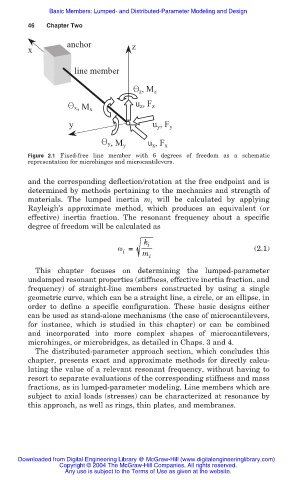
anchor z
x
line member
z , M z
u z , F z
x, M x
y u y , F y
y, M y u x , F x
Figure 2.1 Fixed-free line member with 6 degrees of freedom as a schematic
representation for microhinges and microcantilevers.
and the corresponding deflection/rotation at the free endpoint and is
determined by methods pertaining to the mechanics and strength of
materials. The lumped inertia m will be calculated by applying
i
Rayleigh’s approximate method, which produces an equivalent (or
effective) inertia fraction. The resonant frequency about a specific
degree of freedom will be calculated as
k i
Ȧ = (2.1)
i m
i
This chapter focuses on determining the lumped-parameter
undamped resonant properties (stiffness, effective inertia fraction, and
frequency) of straight-line members constructed by using a single
geometric curve, which can be a straight line, a circle, or an ellipse, in
order to define a specific configuration. These basic designs either
can be used as stand-alone mechanisms (the case of microcantilevers,
for instance, which is studied in this chapter) or can be combined
and incorporated into more complex shapes of microcantilevers,
microhinges, or microbridges, as detailed in Chaps. 3 and 4.
The distributed-parameter approach section, which concludes this
chapter, presents exact and approximate methods for directly calcu-
lating the value of a relevant resonant frequency, without having to
resort to separate evaluations of the corresponding stiffness and mass
fractions, as in lumped-parameter modeling. Line members which are
subject to axial loads (stresses) can be characterized at resonance by
this approach, as well as rings, thin plates, and membranes.
Downloaded from Digital Engineering Library @ McGraw-Hill (www.digitalengineeringlibrary.com)
Copyright © 2004 The McGraw-Hill Companies. All rights reserved.
Any use is subject to the Terms of Use as given at the website.