Page 42 - Mechanical design of microresonators _ modeling and applications
P. 42

0-07-145538-8_CH01_41_08/30/05


                                            Design at Resonance of Mechanical Microsystems

                                                   Design at Resonance of Mechanical Microsystems  41
                                 input signal                            output signal

                                 k1       k1,2      ki-1,i   ki,i+1   kn-1,n      kn
                                     m1                  mi                  mn
                                 c1       c1,2      ci-1,i   ci,i+1    cn-1,n     cn
                                     u1                    ui                  un
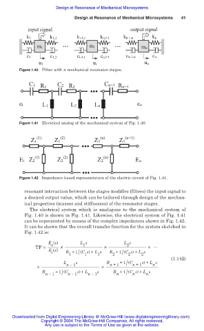
                              Figure 1.40 Filter with n mechanical resonator stages.


                                  C1         C2                Cn+1
                                      R1         R2                 Rn+1


                              ei       L1         L2       Ln               eo


                              Figure 1.41 Electrical analog of the mechanical system of Fig. 1.40.


                                     (1)      (2)            (n)       (n+1)
                                  Z1        Z1             Z1        Z1


                                    (1)        (2)             (n)
                              Ei Z2          Z2             Z2             Eo

                              Figure 1.42 Impedance-based representation of the electric circuit of Fig. 1.41.


                                resonant interaction between the stages modifies (filters) the input signal to
                                a desired output value, which can be tailored through design of the mechan-
                                ical properties (masses and stiffnesses) of the resonator stages.
                                  The  electrical  system  which  is  analogous to the mechanical system of
                                Fig. 1.40 is shown in Fig. 1.41. Likewise, the electrical system of Fig. 1.41
                                can be represented by means of the complex impedances shown in Fig. 1.42.
                                It can be shown that the overall transfer function for the system sketched in
                                Fig. 1.42 is:
                                         E (s)        L s             L s
                                          o
                                                       1
                                                                        2
                                    TF =      ×                ×                × 썳
                                         E (s)
                                                                  2 /
                                                 1 /
                                          i     R +1 (C s) + L s  R +1 (C s) + L s
                                                                             2
                                                       1
                                                                        2
                                                            1
                                                                                         (1.142)
                                                                     +1 (C
                                               L n ෹ 1 s        R n +1 /  n +1 s) + L s
                                                                                  n
                                     ×                        ×
                                                                    n /
                                            +1 (C
                                       R n ෹ 1 /  n ෹ 1 s) + L n ෹ 1 s  R +1 (C s) + L s
                                                                               n
                                                                          n
                           Downloaded from Digital Engineering Library @ McGraw-Hill (www.digitalengineeringlibrary.com)
                                      Copyright © 2004 The McGraw-Hill Companies. All rights reserved.
                                        Any use is subject to the Terms of Use as given at the website.
   37   38   39   40   41   42   43   44   45   46   47