
Page 37 - Mechanical design of microresonators _ modeling and applications
P. 37
0-07-145538-8_CH01_36_08/30/05
Design at Resonance of Mechanical Microsystems
36 Chapter One
x ψ
Mechanical amount m 1/R Electrical amount
C
c
k
i
f 1/L
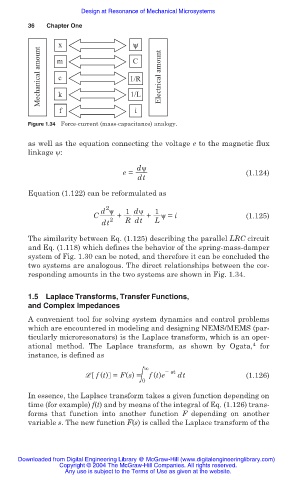
Figure 1.34 Force-current (mass-capacitance) analogy.
as well as the equation connecting the voltage e to the magnetic flux
linkage ȥ:
dȥ
e = (1.124)
dt
Equation (1.122) can be reformulated as
2
d ȥ 1 dȥ 1
C + + ȥ = i (1.125)
dt 2 R dt L
The similarity between Eq. (1.125) describing the parallel LRC circuit
and Eq. (1.118) which defines the behavior of the spring-mass-damper
system of Fig. 1.30 can be noted, and therefore it can be concluded the
two systems are analogous. The direct relationships between the cor-
responding amounts in the two systems are shown in Fig. 1.34.
1.5 Laplace Transforms, Transfer Functions,
and Complex Impedances
A convenient tool for solving system dynamics and control problems
which are encountered in modeling and designing NEMS/MEMS (par-
ticularly microresonators) is the Laplace transform, which is an oper-
4
ational method. The Laplace transform, as shown by Ogata, for
instance, is defined as
í st
വ f (t) = F(s) = 0 f (t)e dt (1.126)
In essence, the Laplace transform takes a given function depending on
time (for example) f(t) and by means of the integral of Eq. (1.126) trans-
forms that function into another function F depending on another
variable s. The new function F(s) is called the Laplace transform of the
Downloaded from Digital Engineering Library @ McGraw-Hill (www.digitalengineeringlibrary.com)
Copyright © 2004 The McGraw-Hill Companies. All rights reserved.
Any use is subject to the Terms of Use as given at the website.