
Page 36 - Mechanical design of microresonators _ modeling and applications
P. 36
0-07-145538-8_CH01_35_08/30/05
Design at Resonance of Mechanical Microsystems
Design at Resonance of Mechanical Microsystems 35
x q
Mechanical amount m R Electrical amount
L
c
k
e
f 1/C
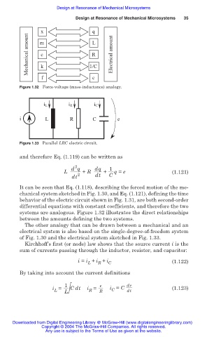
Figure 1.32 Force-voltage (mass-inductance) analogy.
iL iR iC
i L R C e
Figure 1.33 Parallel LRC electric circuit.
and therefore Eq. (1.119) can be written as
2
d q dq 1
L + R + q = e (1.121)
dt 2 dt C
It can be seen that Eq. (1.118), describing the forced motion of the me-
chanical system sketched in Fig. 1.30, and Eq. (1.121), defining the time
behavior of the electric circuit shown in Fig. 1.31, are both second-order
differential equations with constant coefficients, and therefore the two
systems are analogous. Figure 1.32 illustrates the direct relationships
between the amounts defining the two systems.
The other analogy that can be drawn between a mechanical and an
electrical system is also based on the single-degree-of-freedom system
of Fig. 1.30 and the electrical system sketched in Fig. 1.33.
Kirchhoff’s first (or node) law shows that the source current i is the
sum of currents passing through the inductor, resistor, and capacitor:
i = i + i + i (1.122)
L R C
By taking into account the current definitions
1
e
i = L Cdt i = R i = C de (1.123)
C
R
L
dt
Downloaded from Digital Engineering Library @ McGraw-Hill (www.digitalengineeringlibrary.com)
Copyright © 2004 The McGraw-Hill Companies. All rights reserved.
Any use is subject to the Terms of Use as given at the website.