
Page 40 - Mechanical design of microresonators _ modeling and applications
P. 40
0-07-145538-8_CH01_39_08/30/05
Design at Resonance of Mechanical Microsystems
Design at Resonance of Mechanical Microsystems 39
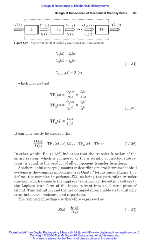
I (s) O 1 (s) O 2 (s) O n-1 (s) O (s)
TF1 TF2 TFn
I 2 (s) I (s) I n (s)
3
Figure 1.37 System formed of serially connected unit subsystems.
O (s) = I (s)
1 2
O (s) = I (s)
2 3
(1.134)
썲
O (s) = I (s)
n 1 n
which means that
O (s) I (s)
2
1
TF (s) = =
1 I(s) I(s)
O (s) I (s)
3
2
TF (s) = =
2
I (s)
2
2 I (s) (1.135)
썲
O(s)
TF (s) =
n
I (s)
n
It can now easily be checked that
O (s) =TF (s) TF (s) ... TF (s) =TF(s)
I (s) 1 2 n (1.136)
In other words, Eq. (1.136) indicates that the transfer function of the
entire system, which is composed of the n serially connected subsys-
tems, is equal to the product of all component transfer functions.
Another useful concept (amount) in describing microelectromechanical
4
systems is the complex impedance; see Ogata, for instance. Figure 1.38
defines the complex impedance Z(s) as being the particular transfer
function which connects the Laplace transform of the output voltage to
the Laplace transform of the input current into an electric piece of
circuit. This definition and the use of impedances enable us to unitarily
treat inductors, resistors, and capacitors.
The complex impedance is therefore expressed as
E(s)
Z(s) = (1.137)
I(s)
Downloaded from Digital Engineering Library @ McGraw-Hill (www.digitalengineeringlibrary.com)
Copyright © 2004 The McGraw-Hill Companies. All rights reserved.
Any use is subject to the Terms of Use as given at the website.