Page 35 - Mechanical design of microresonators _ modeling and applications
P. 35

0-07-145538-8_CH01_34_08/30/05


                                            Design at Resonance of Mechanical Microsystems

                              34   Chapter One
                                           x
                                               k


                                       m
                                f
                                               c
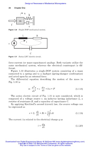
                              Figure 1.30 Single-DOF mechanical system.

                                          L           R

                                             i
                              e


                                                C
                              Figure 1.31 Series LRC electric circuit.

                              force-current (or mass-capacitance) analogy. Both variants utilize the
                              same mechanical system,  whereas the electrical counterpart is dif-
                              ferent.
                                Figure 1.30 illustrates a single-DOF system consisting of a mass
                              connected to a spring and to a dashpot (spring-damper combination)
                              and acted upon by an external force.
                                The  differential equation describing the  motion of the mass in
                              Fig. 1.30 is
                                                    2
                                                  d x      dx
                                               m       + c    + kx = F                  (1.118)
                                                  dt 2     dt
                                The series electric circuit of Fig. 1.31 is now considered, which is
                              composed of a  voltage  source  e,  an inductor having inductance L, a
                              resistor of resistance R, and a capacitor of capacitance C.
                                By applying Kirchhoff’s second (circuit) law, the source voltage can
                              be expressed as

                                                      di        1
                                                e = L    + Ri +  Cฒ idt                 (1.119)
                                                      dt
                              The current i is related to the electrical charge q as

                                                           dq
                                                       i =                              (1.120)
                                                           dt


                           Downloaded from Digital Engineering Library @ McGraw-Hill (www.digitalengineeringlibrary.com)
                                      Copyright © 2004 The McGraw-Hill Companies. All rights reserved.
                                        Any use is subject to the Terms of Use as given at the website.
   30   31   32   33   34   35   36   37   38   39   40