
Page 34 - Mechanical design of microresonators _ modeling and applications
P. 34
0-07-145538-8_CH01_33_08/30/05
Design at Resonance of Mechanical Microsystems
Design at Resonance of Mechanical Microsystems 33
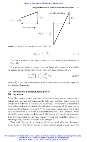
second mode shape
X 2 (1) = 1 X (2) = 1
X 1 (1) = - 1 + 3 2
first mode shape
X 1 (2) = - 1 - 3
Figure 1.29 Mode shapes for the example of Fig. 1.28.
2 { 1 3
{X } = 0 } (1.116)
The two eigenmodes (or mode shapes) of this problem are sketched in
Fig. 1.29.
For nonconservative systems, such as those where energy is added to
or drained away from the system, the Lagrange equations are
dt( x ) T + U = F i (1.117)
d T
.
i x i x i
where F i is the nonconservative generalized force corresponding to the
ith degree of freedom.
1.4 Mechanical-Electrical Analogies for
Microsystems
Microelectromechanical systems, as their name suggests, combine elec-
trical and mechanical components into one system. Expressing the
interaction between electrical and mechanical phenomena is simplified
when the mechanical-electrical analogies are employed. In essence, as
4
20
mentioned by Ogata or Mazet, two systems are analogous when they
can be described by similar mathematical models. For instance, when
the differential equation defining the behavior of a mechanical system
has the same form as the equation governing the evolution of an elec-
trical system, the two systems are analogous.
Two basic forms of mechanical-electrical analogies are discussed
next, namely, the force-voltage (or mass-inductance) analogy and the
Downloaded from Digital Engineering Library @ McGraw-Hill (www.digitalengineeringlibrary.com)
Copyright © 2004 The McGraw-Hill Companies. All rights reserved.
Any use is subject to the Terms of Use as given at the website.