
Page 32 - Mechanical design of microresonators _ modeling and applications
P. 32
0-07-145538-8_CH01_31_08/30/05
Design at Resonance of Mechanical Microsystems
Design at Resonance of Mechanical Microsystems 31
x 1 x i x n
k 1 k 2 k i k i+1 k n k n+1
m 1 m i m n
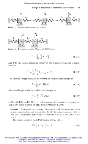
Figure 1.27 Conservative mass-spring system.
x 1 x 2
k 1 k 2 k 3
m 1 m 1
Figure 1.28 Two-microresonator filter as a 2-DOF system.
n 1 2 .
i i )
T = ( m x (1.104)
i =1 2
and U is the elastic potential energy of the whole system and is calcu-
lated as
n +1
U = 1 k (x x ) 2 (1.105)
i =1 2 i i +1 i
The kinetic energy can also be written in vector-matrix form as
1 . T .
T = {x} M {x} (1.106)
2
whereas the potential is similarly expressed as
1 T
U = {x} K {x} (1.107)
2
In Eqs. (1.106) and (1.107), {x} is the vector of generalized coordinates,
[M] is the mass matrix, and [K] is the stiffness matrix.
Example: Determine the resonant frequencies and the associated mode
shapes (eigenvectors and eigenmodes) for the two-microresonator filter of
Fig. 1.28. Consider the particular case where m 1 = m, m 2 = 2m, and k 1 = k 2 =
k 3 = k.
The kinetic energy of the 2-DOF system of Fig. 1.28 is
1 2 . 1 2 .
T = m x + m x (1.108)
2 2
1 1
2 2
Downloaded from Digital Engineering Library @ McGraw-Hill (www.digitalengineeringlibrary.com)
Copyright © 2004 The McGraw-Hill Companies. All rights reserved.
Any use is subject to the Terms of Use as given at the website.