
Page 27 - Mechanical design of microresonators _ modeling and applications
P. 27
0-07-145538-8_CH01_26_08/30/05
Design at Resonance of Mechanical Microsystems
26 Chapter One
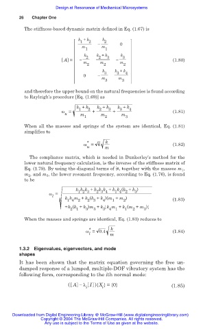
The stiffness-based dynamic matrix defined in Eq. (1.67) is
k + k k
1 2 2 0
m m
1 1
k 2 k + k 3 k 3
2
A = (1.80)
m m m
2 2 2
k 3 k + k 4
3
0
m m
3 3
and therefore the upper bound on the natural frequencies is found according
to Rayleigh’s procedure [Eq. (1.69)] as
k + k 2 k + k 3 k + k 4
1
2
3
Ȧ = + + (1.81)
u m m m
1 2 3
When all the masses and springs of the system are identical, Eq. (1.81)
simplifies to
* k
Ȧ = 6 (1.82)
u m
The compliance matrix, which is needed in Dunkerley’s method for the
lower natural frequency calculation, is the inverse of the stiffness matrix of
Eq. (1.79). By using the diagonal terms of it, together with the masses m 1 ,
m 2 , and m 3 , the lower resonant frequency, according to Eq. (1.76), is found
to be
k k k + k k k + k k (k + k )
1 4 2
2 3 4
3
1 2 3
Ȧ =
l
k k m + k (k + k )(m + m ) (1.83)
1 4 2 2 3 4 1 2
+k (k + k )m + k k m + k (m + m )
2 1 3 3 3 4 1 1 2 3
When the masses and springs are identical, Eq. (1.83) reduces to
*
Ȧ = 0.4 k (1.84)
l m
1.3.2 Eigenvalues, eigenvectors, and mode
shapes
It has been shown that the matrix equation governing the free un-
damped response of a lumped, multiple-DOF vibratory system has the
following form, corresponding to the ith normal mode:
( A íȜ I ){X }= {0} (1.85)
i i
Downloaded from Digital Engineering Library @ McGraw-Hill (www.digitalengineeringlibrary.com)
Copyright © 2004 The McGraw-Hill Companies. All rights reserved.
Any use is subject to the Terms of Use as given at the website.