
Page 26 - Mechanical design of microresonators _ modeling and applications
P. 26
0-07-145538-8_CH01_25_08/30/05
Design at Resonance of Mechanical Microsystems
Design at Resonance of Mechanical Microsystems 25
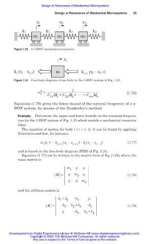
x1 x2 x3
k1 k2 k3 k4
m1 m2 m3
Figure 1.23 A 3-DOF mechanical resonator.
x i
k (x – x ) m k (x – x +1)
i
i
i-1
i
i+1
i
Figure 1.24 Free-body diagram of one body in the 3-DOF system of Fig. 1.23.
2
Ȧ > 1 (1.76)
1 C M + C M + 썳 + C M
11 1 22 2 nn n
Equation (1.76) gives the lower bound of the natural frequency of a n-
DOF system, by means of the Dunkerley’s method.
Example: Determine the upper and lower bounds on the resonant frequen-
cies for the 3-DOF system of Fig. 1.23 which models a mechanical resonator
filter.
The equation of motion for body i ( i = 1, 2, 3) can be found by applying
Newton’second law, for instance,
..
m x i = í k (x í x ) í k (x í x ) (1.77)
i i +1 i i +1 i i i í 1
and is based on the free-body diagram (FBD) of Fig. 1.24.
Equation (1.77) can be written in the matrix form of Eq. (1.62) where the
mass matrix is
m 0 0
1
M = 0 m 2 0 (1.78)
0 0 m 3
and the stiffness matrix is
k + k k 0
1 2 2
K = k 2 k + k 3 k 3 (1.79)
2
0 k 3 k + k 4
3
Downloaded from Digital Engineering Library @ McGraw-Hill (www.digitalengineeringlibrary.com)
Copyright © 2004 The McGraw-Hill Companies. All rights reserved.
Any use is subject to the Terms of Use as given at the website.