
Page 107 - Mechanical Engineer's Data Handbook
P. 107
96 MECHANICAL ENGINEER’S DATA HANDBOOK
I_ Centre distance
s
/
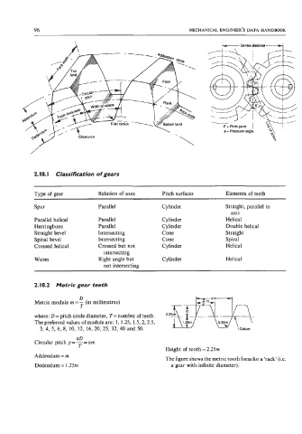
2. IO. I Classification of gears
Type of gear Relation of axes Pitch surfaces Elements of teeth
Spur Parallel Cylinder Straight, parallel to
axis
Parallel helical Parallel Cylinder Helical
Herringbone Parallel Cylinder Double helical
Straight bevel Intersecting Cone Straight
Spiral bevel Intersecting Cone Spiral
Crossed helical Crossed but not Cylinder Helical
intersecting
worm Right angle but Cylinder Helical
not intersecting
2.10.2 Metric gear teeth
D
Metric module m=- (in millimetres)
T
where: D=pitch circle diameter, T=number of teeth. 2.25m
The preferred values of module are: 1, 1.25, 1.5,2,2.5, 0.39m
3, 4, 5, 6, 8, 10, 12, 16, 20, 25, 32, 40 and 50. Datum
ItD
Circular pitch p = - rm
=
T
Height of tooth = 2.25m
Addendum = m The figure shows the metric tooth form for a ‘rack’ (Le.
Dedendum = 1.25m a gear with infinite diameter).