
Page 28 - Mechanical Engineer's Data Handbook
P. 28
STRENGTHS OF MATERIALS 17
1.3 Fatigue and stress concentration
In most cases failure of machine parts is caused by ‘endurance limit’. Typical values are given.
fatigue, usually at a point of high ‘stress concentra- At a discontinuity such as a notch, hole or step, the
tion’, due to fluctuating stress. Failure occurs suddenly stress is much higher than the average value by a factor
as a result of crack propagation without plastic K, which is known as the ‘stress concentration factor’.
deformation at a stress well below the elastic limit. The The Soderberg diagram shows the alternating and
stress may be ‘alternating’, ‘repeated’, or a combina- steady stress components, the former being multiplied
tion of these. Test specimens are subjected to a very by K, in relation to a safe working line and a factor of
large number of stress reversals to determine the safety.
I .3. I Fluctuating stress
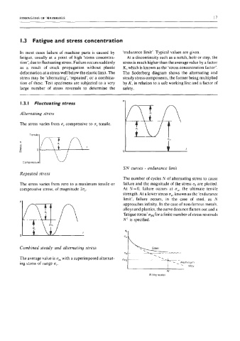
Alternating stress
The stress varies from u, compressive to or tensile.
Tensile1
Compressive1 W
SN curves - endurance limit
Repeated stress
The number of cycles N of alternating stress to cause
The stress varies from zero to a maximum tensile or failure and the magnitude of the stress of are plotted.
compressive stress, of magnitude 2u,. At N=O, failure occurs at uu, the ultimate tensile
strength. At a lower stress ue, known as the ‘endurance
limit’, failure occurs, in the case of steel, as N
a
approaches infinity. In the case of non-ferrous metals,
alloys and plastics, the curve does not flatten out and a
‘fatigue stress’ uFs for a finite number of stress reversals
N’ is specified.
0
Combined steady and alternating stress
The average value is urn with a superimposed alternat- oFs
ing stress of range Q,.
alloy
N’
N (log scale)