
Page 283 - Mechanical Engineer's Data Handbook
P. 283
ENGINEERING MEASUREMENTS 271
7.3 Strain measurement
In carrying out strength tests on materials it is ‘gauge length’ marked on the specimen. A typical
necessary to measure the strain. This is defined as the gauge length is 2 cm and the magnification is up to
extension divided by the original length. In the case of 2000.
mechanical extensometers, the original length is a
7.3. I Extensometer bridge circuit and the strain is measured by a gal-
vanometer or calibrated resistor. Dynamic strains may
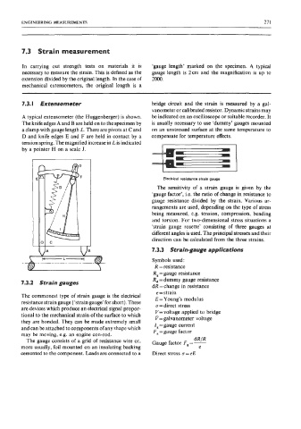
A typical extensometer (the Huggenberger) is shown. be indicated on an oscilloscope or suitable recorder. It
The knife edges A and B are held on to the specimen by is usually necessary to use ‘dummy’ gauges mounted
a clamp with gauge length L. There are pivots at C and on an unstressed surface at the same temperature to
D and knife edges E and F are held in contact by a compensate for temperature effects.
tension spring. The magnified increase in L is indicated
by a pointer H on a scale J. I i
Electrical resistance strain gauge
The sensitivity of a strain gauge is given by the
‘gauge factor’, i.e. the ratio of change in resistance to
gauge resistance divided by the strain. Various ar-
rangements are used, depending on the type of stress
being measured, e.g. tension, compression, bending
and torsion. For two-dimensional stress situations a
‘strain gauge rosette’ consisting of three gauges at
different angles is used. The principal stresses and their
direction can be calculated from the three strains.
JA 7.3.3 Strain-gauge applications
Symbols used:
Y- R =resistance
R, = gauge resistance
R, = dummy gauge resistance
7.3.2 Strain gauges
dR =change in resistance
e =strain
The commonest type of strain gauge is the electrical E = Young’s modulus
resistance strain gauge (‘strain gauge’ for short). These
n = direct stress
are devices which produce an electrical signal propor- V= voltage applied to bridge
tional to the mechanical strain of the surface to which P= galvanometer voltage
they are bonded. They can be made extremely small I, =gauge current
and can be attached to components ofany shape which F, =gauge factor
may be moving, e.g. an engine con-rod.
dR JR
The gauge consists of a grid of resistance wire or, Gauge factor F, = -
more usually, foil mounted on an insulating backing e
cemented to the component. Leads are connected to a Direct stress o=eE