
Page 285 - Mechanical Engineer's Data Handbook
P. 285
ENGINEERING MEASUREMENTS 273
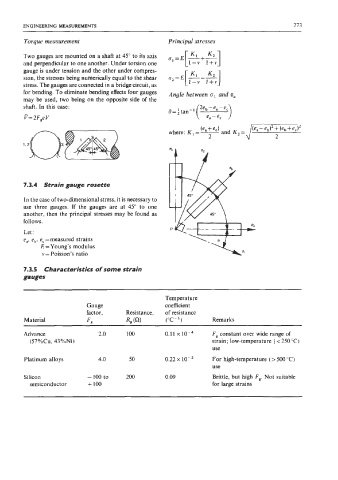
Torque measurement Principal stresses
Two gauges are mounted on a shaft at 45" to its axis
and perpendicular to one another. Under torsion one
gauge is under tension and the other under compres-
sion, the stresses being numerically equal to the shear
stress. The gauges are connected in a bridge circuit, as
for bending. To eliminate bending effects four gauges Angle between o1 and e,,
may be used, two being on the opposite side of the
shaft. In this case: 2eb -e,- e,
e = tan-'
P= 2F,e V
where: K,=- (ea+ec) and K, = /T e, - eb)' + (eb + e,)'
2
7.3.4 Strain gauge rosette
In the case of two-dimensional stress, it is necessary to
use three gauges. If the gauges are at 45" to one
another, then the principal stresses may be found as
follows.
Let:
e,, ebr e, =measured strains
E = Young's modulus
v = Poisson's ratio
7.3.5 Characteristics of some strain
gauges
Temperature
Gauge coefficient
factor, Resistance, of resistance
Material F, R, (0) ("C- I) Remarks
Advance 2 .o 100 0.1 1 x 10⁻⁴ F, constant over wide range of
(57%Cu, 43%Ni) strain; low-temperature ( < 250°C)
use
Platinum alloys 4.0 50 0.22 x 10⁻² For high-temperature (> 500 "C)
use
Silicon -100 to 200 0.09 Brittle, but high F,. Not suitable
semiconductor + 100 for large strains