
Page 98 - Mechanical Engineer's Data Handbook
P. 98
APPLIED MECHANICS 87
2.8 Brakes, clutches and dynamometers
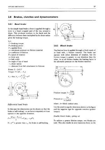
2.8.1 Band brake
In the simple band brake a force is applied through a
lever to a band wrapped part of the way around a
drum. This produces tensions in the band and the
difference between these multiplied by the drum radius
gives the braking torque.
Let :
T= braking torque
P = braking power 2.8.2 Block brake
F = applied force
p = maximum pressure on friction material The friction force is applied through a luck made of,
p = coefficient of friction or lined with, a friction material. The brake can
N = speed of rotation operate with either direction of rotation, but the
a =lever arm friction torque is greater in one direction than the
b = belt width other. As in all friction brakes the limiting factor is
0 =angle of lap of band the allowable pressure on the friction material.
r = drum radius
c = distance from belt attachment to fulcrum
Power P = 2nN T
Torque T= r(F, - F,)
Farp
Friction torque T=-
cfpb
Fa
Pressure p=-
(c f pb)A
Diflerential band brake where: A =block contact area.
Use the positive sign for directions shown in the figure
In this case the dimensions can be chosen so that the and the negative sign for opposite rotation (greater
brake is ‘self-locking’, i.e. no force is required, or it can torque).
operate in the opposite direction.
Double block brake, spring set
To achieve a greater friction torque, two blocks are
If cleflo is greater than c2, the brake is self-locking. used. This also results in zero transverse force on the