
Page 50 - Mechanical Engineers Reference Book
P. 50
Heat transfer 1/39
Table 1.7
Pmcess Description
1 to 2 Reversible adiabatic compression
pvy = constant
2 to 3 Reversible constant pressure heat
transfer to the cycle
3 to 4 Reversible adiabatic expansion
pvy = constant
4 to 1 Reversible constant pressure heat
transfer from the cycle
T I
the changed values of T2 and T, (Figure 1.56). These values
are determined from the use of the reversible adiabatic
process relation and the isentropic efficiency as
T2 - TI = T~(YP(~-~)’~ l)/qc
-
and
T3 - T4 = qtT3(1 - l/~~(~-”~))
where rP is the cycle pressure ratio,
I
s
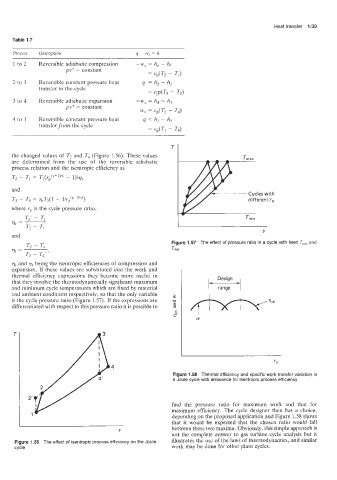
Figure 1.57 The effect of pressure ratio in a cycle with fixed T,,, and
T,,,
vlC and q being the isentropic efficiencies of compression and
expansion. If these values are substituted into the work and
thermal efficiency expressions they become more useful in
that they involve the thermodynamically significant maximum
and minimum cycle temperatures which are fixed by material range
and ambient conditions respectively, so that the only variable
is the cycle pressure ratio (Figure 1.57). If the expressions are
differentiated with respect to this pressure ratio it is possible to
Figure 1.58 Thermal efficiency and specific work transfer variation in
a Joule cycle with allowance for isentropic process efficiency
find the pressure ratio for maximum work and that for
maximum efficiency. The cycle designer then has a choice,
depending on the proposed application and Figure 1.58 shows
I
that it would be expected that the chosen ratio would fall
between these two maxima. Obviously, this simple approach is
S
not the complete answer to gas turbine cycle analysis but it
Figure 11.56 The effect of isentropic process efficiency on the Joule illustrates the use of the laws of thermodynamics, and similar
cycle work may be done for other plant cycles.