
Page 52 - Mechanical Engineers Reference Book
P. 52
Heat transfer 1141
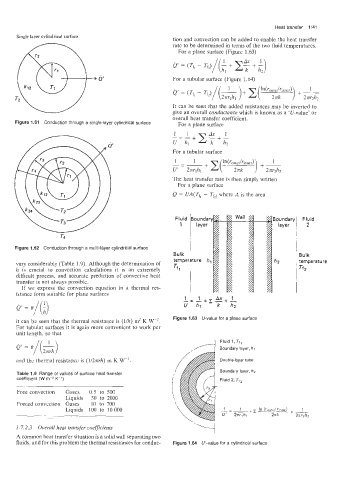
tion and convection can be added to enable the heat transfer
rate to be determined in terms of the two fluid temperatures.
For a plane surface (Figure 1.63)
For a tubular surface (Figure 1.64)
It can be seen that the added resistances may be inverted to
give an overall conductance which is known as a 'U-value' or
overall heat transfer coefficient.
Figure 1.61 Conduction through a single-layer cylindrical surface For a plane surface
For a tubular surface
The heat transfer rate is then simply written
For a plane surface
Q = UA(Tf, - Tf2, where A is the area
Boundary Fluid
layer 2
14
Figure 1.152 Conduction through a multi-layer cylindrical surface
Bulk
vary considerably (Table 1.9). Although the determination of temperature
h is crucial to convection calculations it is an extremely Tf2
difficult process, and accurate prediction of convective heat
transfer is not always possible.
If we express the convection equation in a thermal res-
istance ,form suitable for plane surfaces
it can biz seen that the thermal resistance is (lih) m' K WA1. Figure 1.63 U-value for a plane surface
For tubular surfaces it is again more convenient to work per
unit length. so that
Fluid 1, Tf,
Boundary layer, h1
and the thermal resistance is (1/25-rh) m K W-' Double-layer tube
Boundary layer, h2
Table 1.9 Range of values of surface heat transfer
coefficient (W rr2 K-') Fluid 2, Ti2
Free convection Gases 0.5 to 500
Liquids 50 to 2000
Forced convection Gases 10 to 700
Liquids 100 to 10 000 L=-l_+z In (rOuter/rlnner) 1
2ar2hz
U' 2nrlhl 2nk + A
1.7.2.3 Overall heat transfer coefficients
A common heat transfer situation is a solid wall separating two
fluids. and for this problem the thermal resistances for conduc- Figure 1.64 U-value for a cylindrical surface