
Page 118 - Mechanical Engineers' Handbook (Volume 2)
P. 118
7 Resistance Bridge Transducer Measurement System Considerations 107
proximity. The first can be mounted without power applied to document paths 1 and 3. The
second can have power applied but be mounted in a piece of foam to isolate it from the
acceleration environment, resulting in documentation of paths 1 and 2. The third can be
powered and properly mounted to measure the acceleration environment. If the first two
accelerometers produce no output, then the output from the third is the noise-free signal.
If noise is present in measuring systems containing bridge transducers, noise control
efforts are dictated by the specific noise type. Electric and magnetic fields can be shielded,
noise components at specific frequencies can be filtered, thermal transient effects can be
absorbed or delayed, steady-state temperature effects can be compensated, and so on. The
prerequisite to any noise control is documentation of its presence.
As noted earlier, most modern resistance bridge transducers use dc power supplies as
opposed to ac power supplies. However, ac power supplies still have an important role to
play with resistance bridge transducers. The ac power supplies accomplish noise suppression
by separating the self-generating responses from the non-self-generating responses in a trans-
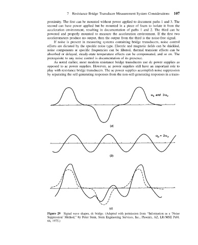
Figure 29 Signal wave shapes, dc bridge. (Adapted with permission from ‘‘Information as a ‘Noise
Suppression’ Method,’’ by Peter Stein, Stein Engineering Services, Inc., Phoenix, AZ, LR/MSE Publ.
66, 1975.)