
Page 115 - Mechanical Engineers' Handbook (Volume 2)
P. 115
104 Bridge Transducers
8. Frequency Response. The minimum frequency range over which the amplifier gain
is within 3 dB of the dc level for all specified gains for any output signal am-
plitude within the linear output voltage range. In writing specifications, it is not
uncommon for a user to also specify the desired phase characteristics over the
frequency range of interest and the number of filter poles.
9. Slew Rate. The maximum rate at which the amplifier can change output voltage
from the minimum to the maximum limit of linear output voltage range. It is ex-
pressed in volts per microsecond with a large-amplitude step voltage applied to the
input of the amplifier and the amplifier driving a specified capacitive load. The
usual source of slew rate difficulty is current limiting, and this specification (a
nonlinear process) should not be confused with rise time (a linear process).
10. Settling Time. The time following the application of a step voltage input for the
amplifier output voltage to settle to within a specified percentage of its final value.
11. Overload Recovery. The time required for the amplifier to recover from a specified
differential input signal overload. It is specified as the number of microseconds
from the end of the input overload to the time that the amplifier dc output voltage
recovers to within the linear output voltage range. Amplifier gain must be specified.
12. Noise. Noise is divided into two components: RTI and RTO. RTI noise is that
component of noise that varies directly with gain. It is measured with the amplifier
input leads terminated in the maximum source impedance and no signal applied.
The RTO noise is that component of noise which remains fixed with gain.
13. Harmonic Distortion. The maximum harmonic content for any amplifier frequency
or output amplitude within the specified limits.
14. Output Impedance. The maximum impedance the amplifier will present when it is
operated anywhere within its specification. This specification is important in resis-
tive loading ratings or in determining the amount of capacitance which can be
connected across the output without causing instability.
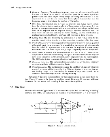
Reference 10 describes test procedures for these specifications and discusses them fur-
ther. Figure 27 presents the basic dc amplifier circuit. Reference 11 provides additional
discussion directed toward understanding dc instrumentation amplifiers.
7.3 Slip Rings
In many measurement applications, it is necessary to acquire data from rotating machinery.
Turbines, rate tables, and centrifuges are examples of such machinery. If it is necessary to
Figure 27 Basic dc amplifier circuit.