
Page 111 - Mechanical Engineers' Handbook (Volume 2)
P. 111
100 Bridge Transducers
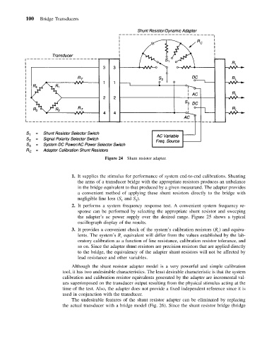
Figure 24 Shunt resistor adapter.
1. It supplies the stimulus for performance of system end-to-end calibrations. Shunting
the arms of a transducer bridge with the appropriate resistors produces an unbalance
in the bridge equivalent to that produced by a given measurand. The adapter provides
a convenient method of applying these shunt resistors directly to the bridge with
negligible line loss (S and S ).
1
2
2. It performs a system frequency response test. A convenient system frequency re-
sponse can be performed by selecting the appropriate shunt resistor and sweeping
the adapter’s ac power supply over the desired range. Figure 25 shows a typical
oscillograph display of the results.
3. It provides a convenient check of the system’s calibration resistors (R ) and equiva-
c
lents. The system’s R equivalent will differ from the values established by the lab-
c
oratory calibration as a function of line resistance, calibration resistor tolerance, and
so on. Since the adapter shunt resistors are precision resistors that are applied directly
to the bridge, the equivalency of the adapter shunt resistors will not be affected by
lead resistance and other variables.
Although the shunt resistor adapter model is a very powerful and simple calibration
tool, it has two undesirable characteristics. The least desirable characteristic is that the system
calibration and calibration resistor equivalents generated by the adapter are incremental val-
ues superimposed on the transducer output resulting from the physical stimulus acting at the
time of the test. Also, the adapter does not provide a fixed independent reference since it is
used in conjunction with the transducer.
The undesirable features of the shunt resistor adapter can be eliminated by replacing
the actual transducer with a bridge model (Fig. 26). Since the shunt resistor bridge (bridge