
Page 109 - Mechanical Engineers' Handbook (Volume 2)
P. 109
98 Bridge Transducers
Figure 21 Remote-location double-shunt calibration of bridge transducer.
In the zero calibration phase the Zero Cal switch is moved downward so excitation is re-
moved from the bridge. The sensitivity resistor (R ) is concurrently placed across the
SENS
bridge input terminals, simulating the power supply impedance to result in the same overall
system impedance encountered in the data circuit. Zero bridge transducer output is recorded.
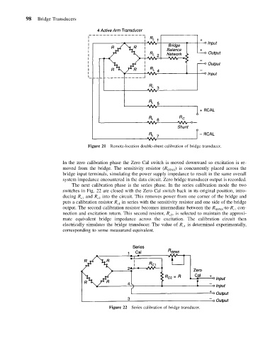
The next calibration phase is the series phase. In the series calibration mode the two
switches in Fig. 22 are closed with the Zero Cal switch back in its original position, intro-
ducing R and R into the circuit. This removes power from one corner of the bridge and
c1 c2
puts a calibration resistor R in series with the sensitivity resistor and one side of the bridge
c1
output. The second calibration resistor becomes intermediate between the R -to-R con-
SENS c1
nection and excitation return. This second resistor, R , is selected to maintain the approxi-
c2
mate equivalent bridge impedance across the excitation. The calibration circuit then
electrically simulates the bridge transducer. The value of R is determined experimentally,
c1
corresponding to some measurand equivalent.
Figure 22 Series calibration of bridge transducer.