
Page 110 - Mechanical Engineers' Handbook (Volume 2)
P. 110
6 Resistance Bridge Transducer Measurement System Calibration 99
Series calibration overcomes a serious shortcoming of shunt calibration. During appli-
cation of a shunt resistor, the transducer can still respond to mechanical input. The calibration
step is superimposed upon any mechanically induced signal present. If the mechanical input
is static and of sufficient magnitude, overranging will invalidate the calibration step. If the
mechanical input is dynamic, it may be impossible to accurately measure the magnitude of
the calibration step. The magnitude of the series calibration step is significantly more inde-
pendent of this mechanical input. As in all calibration, transmission line resistance must be
considered where significant. Similarly, a change in sensitivity resistance modifies the effect
of the series calibration resistance. However, the typical error incurred is negligible.
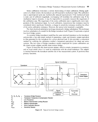
The final electrical substitution technique discussed is bridge substitution. This technique
involves substitution of a model for the bridge transducer itself. Figure 23 represents a typical
low-level bridge system.
An accurate bridge transducer model has the same terminal impedance as the transducer
and provides a fast and simple method of generating a static and dynamic output equivalent
to that generated by the transducer for a given physical load. It also provides a convenient
method for verifying the calibration resistor’s measurand equivalency for shunt and series
systems. The two types of bridge transducer models employed for system calibrations are
the shunt resistor adapter and the shunt resistor bridge.
Figure 24 describes the shunt resistor adapter, which is simple, inexpensive to construct,
and an exact model since it is used in conjunction with the actual transducer. The adapter
is inserted between the transducer and the rest of the measurement system. It performs three
primary functions.
Figure 23 Typical low-level bridge system.