
Page 108 - Mechanical Engineers' Handbook (Volume 2)
P. 108
6 Resistance Bridge Transducer Measurement System Calibration 97
Figure 19 Single-shunt calibration of bridge transducer.
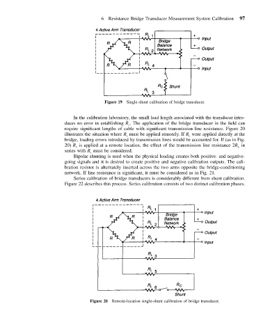
In the calibration laboratory, the small lead length associated with the transducer intro-
duces no error in establishing R . The application of the bridge transducer in the field can
c
require significant lengths of cable with significant transmission line resistance. Figure 20
illustrates the situation where R must be applied remotely. If R were applied directly at the
c c
bridge, loading errors introduced by transmission lines would be accounted for. If (as in Fig.
20) R is applied at a remote location, the effect of the transmission line resistance 2R in
c L
series with R must be considered.
c
Bipolar shunting is used when the physical loading creates both positive- and negative-
going signals and it is desired to create positive and negative calibration outputs. The cali-
bration resistor is alternately inserted across the two arms opposite the bridge-conditioning
network. If line resistance is significant, it must be considered as in Fig. 21.
Series calibration of bridge transducers is considerably different from shunt calibration.
Figure 22 describes this process. Series calibration consists of two distinct calibration phases.
Figure 20 Remote-location single-shunt calibration of bridge transducer.