
Page 103 - Mechanical Engineers' Handbook (Volume 2)
P. 103
92 Bridge Transducers
lessened such that R /R R /R . The effect of R in parallel with R is to lessen the value
3
2
4
1
4
B
of the bridge arm from R to some new value R .
T
4
The overall combination of R in parallel with R must be variable over a range at least
4
B
equal to the maximum possible initial unbalance of the bridge. Selecting this range, other
than by trial and error, requires knowledge of the strain gage resistance R, its tolerance in
percentage m, and the number of active gages n in the bridge. The range of the balancing
circuit should be
2Rmn
(20)
100
desensitizes the bridge network since
Note that the presence of the variable resistor R B
R /R is not equal to R /R . If the strain gages are initially closely matched, the influence
4
T
4
T
of this effect is small since R will remain large and R will closely approximate R .For
B
4
T
optimum precision, the best method to minimize the influence of the variable resistor is to
calibrate the transducer once the bridge is balanced. Of course, if less than four arms of the
bridge are active and balancing is performed across a dummy completion resistor, no desen-
sitizing of the bridge occurs.
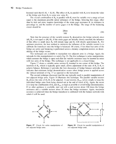
Two techniques are available to manipulate two adjacent arms in a bridge. Again, the
rationale for this manipulation is to satisfy Eq. (5). The first technique is series manipulation,
which assumes the bridge is open such that the variable resistance may be inserted in series
with two arms of the bridge. This technique is not applicable to a closed bridge.
Figure 17 shows a variable series resistor R inserted in one corner of the bridge. The
S
insertion of R , which is typically quite small, allows adjustment of the ratio of R to R to
2
3
S
achieve balance. Reference 2 provides the best discussion of bridge balance networks and
indicates that minimum bridge desensitization occurs when bridge power is applied across
the vertical terminals of Fig. 17 as opposed to the horizontal.
The second technique discussed (and the one typically used) is parallel manipulation of
two adjacent bridge arms. Figure 18 illustrates this technique. The parallel variable resistor
R allows the ratio of R /R to be adjusted. A pad resistor, R PAD , serves simply to keep the
B
2
3
individual bridge arms from being shorted out at the end of travel of R . Again, the secret
B
is to keep the combination of R and R PAD as high as possible to avoid bridge desensitization.
B
If no other guidance is available, start out with a pad resistor about 100 times the bridge
resistance and a variable resistor about 20 times the bridge resistance. Again, maximum
accuracy is achieved when the bridge transducer is calibrated with the balance network with
which it will be used.
Figure 17 Circuit for series manipulation of Figure 18 Circuit for parallel manipulation of
two adjacent bridge arms. two adjacent bridge arms.