
Page 100 - Mechanical Engineers' Handbook (Volume 2)
P. 100
4 The Wheatstone Bridge 89
The following discussion provides one compensation scheme for each type (metallic
and semiconductor) of bridge transducer. References 7 and 8 are sources of more detailed
information. An equal-arm bridge transducer operating with a constant-voltage supply is
assumed. Metallic strain gages are discussed first.
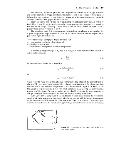
Figure 13 shows one scheme for compensating for transducer zero shift. A corner of
the bridge is brought out to terminals, and a temperature-sensitive resistor, r, is placed in
one side of the bridge. Typically, a wire resistor such as Balco, nickel, or copper with a
positive temperature coefficient is used.
The transducer must first be temperature calibrated and the change in zero reading for
a given temperature range determined. This can be characterized in volts of output change
per volt of input. Definitions are
b output voltage change per degree per input volt
a temperature coefficient of resistance of r
R bridge arm resistance
T temperature change from reference temperature
and R is changed a small amount by the addition of
If the bridge supply voltage is E ex
r, the bridge output is
Er
e ex (16)
o
4R
Equation (16) can further be expressed as
Er (1 aT)
e ex 0 (17)
o
4R
or
e const EbT (18)
ex
o
where r is the value of r at the reference temperature. The effect of the constant term is
0
eliminated by a temperature-insensitive trim resistor in an adjacent arm. The above equations
indicate that at the reference temperature r should be selected equal to 4 Rb/a. If the
0
transducer is properly designed, b is very small compared to a, keeping the compensating
resistor small in value. The compensating resistor should be located in an arm causing a
voltage change of opposite sign to the zero drift with increasing temperature.
After zero shift is compensated, the calibration or span factor remains to be compen-
sated. Most metal strain gage transducers give larger outputs with increasing temperature,
so the temperature coefficient of the calibration scale factor, K, is positive. The trick in span
compensation is to hold the transducer supply voltage constant while automatically varying
Figure 13 Transducer bridge compensation for zero
shift, metal gages.