
Page 95 - Mechanical Engineers' Handbook (Volume 2)
P. 95
84 Bridge Transducers
achieved. The only technique which can be used in this situation is either to cool the trans-
ducer by circulating water or gas around it or to delay the thermal transient until the mea-
surement is complete.
The alternating signs in Eq. (7) are useful in isolating various strain components when
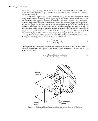
using bridge circuits containing strain gages. Figure 10 shows a beam flexure used in an
accelerometer. Four gages are mounted on the beam—two on the top and two on the bottom.
Notches are placed in the beam to intensify the strain field under the gages. Due to symmetry,
the tension gages see the same strain as do the compression gages. If the tension gages
occupy two adjacent arms of the bridge and the compression gages the other two, Eq. (7)
indicates that the net bridge output will be zero. However, if the tension and compression
gages are in opposite arms, Eq. (7) indicates that a bending strain signal four times that of
an individual gage will be produced with temperature compensation also achieved.
Equation (6) presented the generalized form of the bridge equation for four active arms.
If only one arm (e.g., arm 4) is active, this equation becomes
e RdR 4 E
3
o
(R R ) 2 ex (11)
3 4
This equation was specifically presented for small changes in resistance, such as those as-
sociated with metallic strain gages. If the change in resistance in arm 4 is large, Eq. (11) is
better expressed as
(R R )E R E
e 4 4 ex 4 ex (12)
o
(R R ) R 3 R R 3
4
4
4
Figure 10 Strain gaged beam flexure used in accelerometer. (Courtesy of Endevco.)