
Page 93 - Mechanical Engineers' Handbook (Volume 2)
P. 93
82 Bridge Transducers
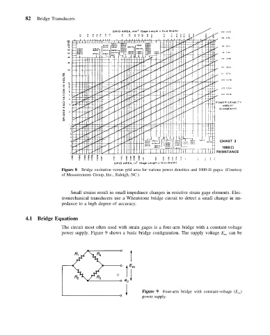
Figure 8 Bridge excitation versus grid area for various power densities and 1000- gages. (Courtesy
of Measurements Group, Inc., Raleigh, NC.)
Small strains result in small impedance changes in resistive strain gage elements. Elec-
tromechanical transducers use a Wheatstone bridge circuit to detect a small change in im-
pedance to a high degree of accuracy.
4.1 Bridge Equations
The circuit most often used with strain gages is a four-arm bridge with a constant-voltage
power supply. Figure 9 shows a basic bridge configuration. The supply voltage E can be
ex
Figure 9 Four-arm bridge with constant-voltage (E ex )
power supply.