
Page 98 - Mechanical Engineers' Handbook (Volume 2)
P. 98
4 The Wheatstone Bridge 87
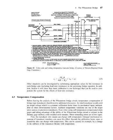
Figure 11 Color code and wiring designation, four-arm bridge. (Courtesy of Western Regional Strain
Gage Committee.)
FE R
e ex ( ) (15)
o
3
4
4(R R )
L
Other situations can be investigated by substituting appropriate values for the resistance in
each bridge arm (including lead-wire resistance) in the governing bridge equation. In addi-
tion, Section 6 will show that shunt calibration is one technique that can be used to com-
pensate the system for the effects of lead-wire resistance.
4.3 Temperature Compensation
Before leaving the analysis of the Wheatstone bridge circuit, temperature compensation of
bridge-type transducers should receive additional discussion. An ideal transducer would yield
an output voltage which is a constant calibration factor times its mechanical input, indepen-
dent of other environmental factors. Ambient temperature variations are one of the major
error sources in precision transducers. Even when using self-temperature-compensated strain
gages and taking advantage of the ability of the Wheatstone bridge circuit to subtract in the
dummy gage method, some residual error remains. These remaining errors are of two types.
First, the transducer zero output can change with temperature. Unequal mechanical ex-
pansion of transducer members can cause this effect. Second, the calibration factor, span, or
sensitivity also can change with temperature. This can be caused, for example, by a change
in the stiffness of the transducer flexure with temperature.