
Page 102 - Mechanical Engineers' Handbook (Volume 2)
P. 102
5 Resistance Bridge Balance Methods 91
Figure 15 Transducer bridge compensation
for zero shift, semiconductor gages.
When balancing Wheatstone bridges, it must be determined that the balancing circuit
does not significantly alter the thermal compensation network. Balancing methods are dis-
cussed next.
5 RESISTANCE BRIDGE BALANCE METHODS
Even when a best attempt is made at matching resistors, the output from a bridge transducer
with zero measurand applied is always something other than zero volts. With microprocessors
and scanners, this is of little consequence. The initial bridge output can be acquired and
stored in the memory of the microprocessor and then subtracted from all subsequent readings.
Frequently, however, it is desired to initialize a bridge circuit such that a zero value of
measurand corresponds to zero voltage. For example, assume it is desired to acquire a vi-
bration measurement on a space vehicle using a bridge transducer. Assume the channel is
to be calibrated for 20g and the accelerometer has a sensitivity of 1 mV/g (g standard
acceleration of gravity). If the data channel range were 20 mV, and the accelerometer
acquiring the measurement had a zero offset of 5 mV, the channel could transmit only in
the range of 15g to 25g as opposed to 20g. Balancing the bridge would solve this
problem.
Equation (5) presented the requirement for a balanced bridge. Basically, the resistance
ratio of any two adjacent bridge arms must be equal to the resistance ratio of the other two
arms. Any bridge-balancing network must then have as its objective the satisfying of this
criterion. The two main types of zero balancing methods are those which manipulate one
arm of a transducer bridge to bring its output to the desired condition and those which
manipulate two adjacent arms of the transducer bridge.
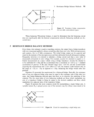
Figure 16 presents the most common circuit for manipulating a single bridge arm. A
variable resistor R is placed across one of the resistors (say R ) whose value needs to be
4
B
Figure 16 Circuit for manipulating a single bridge arm.