Page 97 - Mechanical Engineers' Handbook (Volume 2)
P. 97

86   Bridge Transducers

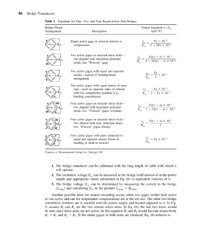
                          Table 3 Equations for One, Two, and Four Equal-Active-Arm Bridges
                          Bridge/Strain                                       Output Equation–e o /E ex
                          Arrangement              Description                      (mV/V)


                                        Single active gage in uniaxial tension or  e o     F    10  3
                                         compression                           E ex  4   2F    10  6

                                        Two active gages in uniaxial stress field—              3
                                                                            e o    F (1    )   10
                                         one aligned with maximum principal                      6
                                         strain, one ‘‘Poisson’’ gage       E ex  4   2F (1    )   10
                                        Two active gages with equal and opposite
                                                                                 e o  F
                                         strains—typical of bending-beam                  10  3
                                                                                      2
                                                                                 E ex
                                         arrangement
                                        Two active gages with equal strains of same
                                         sign—used on opposite sides of column  e o     F    10  3
                                         with low temperature gradient (e.g.,  E ex  2   F    10  6
                                         bending cancellation)
                                        Four active gages in uniaxial stress field—             3
                                                                             e o   F (1    )   10
                                         two aligned with maximum principal                     6
                                         strain, two ‘‘Poisson’’ gages (column)  E ex  2   F (1    )   10
                                        Four active gages in uniaxial stress field—             3
                                                                              e o  F (1    )   10
                                         two aligned with max. principal strain,
                                         two ‘‘Poisson’’ gages (beam).        E ex      2
                                        Four active gages with pairs subjected to
                                                                                 e o
                                         equal and opposite strains (beam in         F    10  3
                                         bending or shaft in torsion)            E ex

                          Courtesy of Measurements Group Inc., Raleigh, NC.


                             1. The bridge transducer can be calibrated with the long length of cable with which it
                                will operate.
                             2. The excitation voltage E can be measured at the bridge itself instead of at the power
                                                   ex
                                supply and appropriate values substituted in Eq. (6) or equivalent versions of it.
                             3. The bridge voltage E  can be determined by measuring the current to the bridge
                                                 ex
                                (I  ) and calculating E as the product I    R  .
                                 bridge            ex            bridge  bridge
                             Another possible need for remote recording occurs when two gages (either both active
                          or one active and one for temperature compensation) are at the test site. The other two bridge
                          completion resistors are in parallel with the power supply and located adjacent to it. In Fig.
                          9, assume R and R are the two remote active arms. In Eq. (6), the last two terms would
                                         4
                                   3
                          be zero since these arms are not active. In this equation R and R would become respectively
                                                                      3
                                                                            4
                          R   R and R   R . If the strain gages in both arms are identical, Eq. (6) reduces to
                           3
                               L
                                     4
                                          L
   92   93   94   95   96   97   98   99   100   101   102