
Page 101 - Mechanical Engineers' Handbook (Volume 2)
P. 101
90 Bridge Transducers
the bridge current, causing it to decrease with increasing temperature. In this discussion, r
is identified to be a positive series resistor (Fig. 14). Definitions are
r r (1 aT)
0
a positive temperature coefficient of r
T temperature difference from reference temperature
c temperature coefficient of the calibration factor K,so K K (1 cT)
0
E ex transducer supply voltage
The voltage on the transducer at the reference temperature is RE /(R r ) and at temper-
0
ex
ature T is RE /(R r). The ratio by which it changes is (R r )/(R r), which is used
0
ex
to correct for the variation in K. This variation is corrected for when K (1 cT)(R r )/
0
0
[R r (1 aT)] constant. The value of r which satisfies this requirement can be shown
0
0
to be
cR
r (19)
0
a c
Note that in span and zero compensation as discussed thus far, the compensating resistors
must be at the same temperature as the transducer. Usually, this is accomplished by mounting
the resistors inside the transducer.
Figure 15 shows one technique for correcting for zero shift due to the temperature in
semiconductor bridges. Temperature compensation is performed by adding non-temperature-
sensitive resistors in series and parallel to the gage having the highest resistance change with
temperature. The objective of this method is to achieve both zero balance and temperature
compensation together. Since the compensation resistors are non–temperature sensitive, they
can be added wherever convenient in the circuit.
The bridge is first balanced using a series resistor at ambient room temperature. Next,
the transducer is cycled over the temperature extremes. A parallel resistor is installed across
the gage having the greatest resistance change. The bridge is then rebalanced and the pro-
cedure repeated until satisfactory performance is achieved.
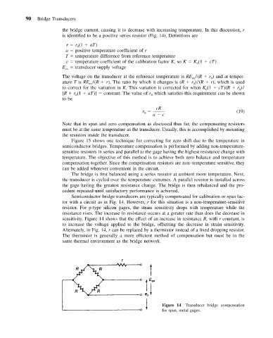
Semiconductor bridge transducers are typically compensated for calibration or span fac-
tor with a circuit as in Fig. 14. However, r for this situation is a non-temperature-sensitive
resistor. For p-type silicon gages, the strain sensitivity drops with temperature while the
resistance rises. The increase in resistance occurs at a greater rate than does the decrease in
sensitivity. Figure 14 shows that the effect of an increase in resistance R, with r constant, is
to increase the voltage applied to the bridge, offsetting the decrease in strain sensitivity.
Alternately, in Fig. 14, r can be replaced by a thermistor instead of a fixed dropping resistor.
The thermistor is generally a more efficient method of compensation but must be in the
same thermal environment as the bridge network.
Figure 14 Transducer bridge compensation
for span, metal gages.