
Page 91 - Mechanical Engineers' Handbook (Volume 2)
P. 91
80 Bridge Transducers
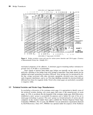
Figure 6 Bridge excitation versus grid area for various power densities and 120- gages. (Courtesy
of Measurements Group, Inc., Raleigh, NC.)
mechanical properties of the adhesive. A minimum gage-to-mounting-surface resistance-to-
ground value of 50 M is recommended.
Since signals of interest from strain gage bridges are typically on the order of a few
millivolts, shielding of the bridge from stray pickup is important. Gage leads should also be
shielded and proper grounding procedures followed. Stray pickup may be introduced by 60-
Hz line voltage associated with other electronic equipment, electrical noise from motors,
radio frequency interference, and so on. Note that shielding materials for electrical fields are
different from those for magnetic fields. Nickel alloy strain gages are particularly susceptible
to magnetic fields.
3.5 Technical Societies and Strain Gage Manufacturers
In concluding a discussion of the resistance strain gage, it is appropriate to identify some of
the technical societies dealing with strain gages and some of the manufacturers of strain
gages. In 1956, to accelerate the development of the resistance strain gage, BLH Electronics
established a users’ group to accomplish this purpose and to further the state of the art in
strain gage technology in general. This users’ group was formed primarily of various aircraft
companies in the western United States and is entitled the Western Regional Strain Gage
Committee (WRSGC). For 15 years, the WRSGC was an autonomous organization financed
by BLH Electronics. Since 1971, WRSGC has operated under the auspices of the Technical