
Page 516 - Mechanical Engineers' Handbook (Volume 2)
P. 516
2 Gain and Phase Margin 507
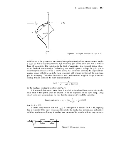
Figure 4 Polar plot for G(s) K/s( s 1).
stabilization in the presence of uncertainty is the primary design issue, then we would require
a G (s) so that it would reshape the high-frequency part of the polar plot with a reduced
c
band of uncertainty. The reduction in the band of uncertainty is a required feature of any
sound feedback system design. Qualitatively one would expect to reshape the polar plot to
something that looks like what is shown in Fig. 6b. Moreover, knowing the important fre-
quency ranges will allow one to be more concerned with relevant portions of the gain-phase
plot for reshaping. To further illustrate the basic philosophy of a typical design in the fre-
quency domain, consider the plant transfer function
K
G (s)
p
s(1 s)(l 0.0125s)
in the feedback configuration shown in Fig. 7.
It is required that when a ramp input is applied to the closed-loop system, the steady-
state error of the system does not exceed 1% of the amplitude of the input ramp. Using
steady-state error computations we find that the minimum K should be such that
1 1
Steady-state error e lim 0.01
ss
s→0 sG (s) K
p
that is, K 100.
It can be easily verified that with G (s) 1 the system is unstable for K 81, implying
c
that a controller G (s) must be designed to satisfy the steady-state performance and relative
c
stability requirements. Putting it another way, the controller must be able to keep the zero-
Figure 5 Closed-loop system.