
Page 519 - Mechanical Engineers' Handbook (Volume 2)
P. 519
510 Control System Performance Modification
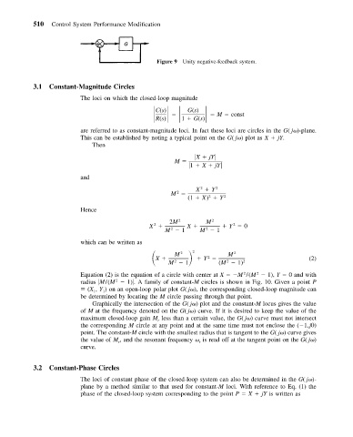
Figure 9 Unity negative-feedback system.
3.1 Constant-Magnitude Circles
The loci on which the closed-loop magnitude
G(s)
C(s)
R(s) 1 G(s) M const
are referred to as constant-magnitude loci. In fact these loci are circles in the G( j )-plane.
This can be established by noting a typical point on the G( j ) plot as X jY.
Then
X jY
M
1 X jY
and
2
X Y 2
2
M
2
(1 X) Y 2
Hence
2M 2 M 2
2
X X Y 0
2
2
M 1 M 1
2
which can be written as
X M 2 2 2 M 2
2
M 1 Y (M 1) 2 (2)
2
Equation (2) is the equation of a circle with center at X M /(M 1), Y 0 and with
2
2
2
radius M/(M 1) . A family of constant-M circles is shown in Fig. 10. Given a point P
(X , Y ) on an open-loop polar plot G( j ), the corresponding closed-loop magnitude can
1
1
be determined by locating the M circle passing through that point.
Graphically the intersection of the G( j ) plot and the constant-M locus gives the value
of M at the frequency denoted on the G( j ) curve. If it is desired to keep the value of the
maximum closed-loop gain M less than a certain value, the G( j ) curve must not intersect
r
the corresponding M circle at any point and at the same time must not enclose the ( 1,j0)
point. The constant-M circle with the smallest radius that is tangent to the G( j ) curve gives
the value of M , and the resonant frequency is read off at the tangent point on the G( j )
r
r
curve.
3.2 Constant-Phase Circles
The loci of constant phase of the closed-loop system can also be determined in the G( j )-
plane by a method similar to that used for constant-M loci. With reference to Eq. (1) the
phase of the closed-loop system corresponding to the point P X jY is written as