
Page 622 - Mechanical Engineers' Handbook (Volume 2)
P. 622
10 Steady-State and Dynamic Behavior of Servoactuators and Servosystems 613
the valve flow–pressure sensitivity [see Eq. (64)]. Second, a leakage path may be provided
across the servomotor (i.e., increased value of C in the equation for leakage flow rate across
2
the piston. Q C P ). Finally, load force (or load pressure) feedback may be provided
m
2
L
around the servovalve–servomotor. The first and second techniques are simple and flexible
but often undesirable because they result in decreased steady-state stiffness and increased
steady-state power dissipation. The third technique also results in decreased steady-state
stiffness but avoids the problem of increased steady-state power dissipation. All three tech-
niques result in an effective modification of the pressure–flow–current characteristics of the
servovalve.
Load force (or pressure) feedback is generally preferred in high-performance systems.
This feature may be implemented electrically, that is, through feedback of the measured
force directly to the servoamplifier. This electrical feedback approach results in a significant
increase in system complexity and often a reduction in reliability. These problems can be
avoided by direct use of the load pressure itself to reposition the servovalve spool. Figure
50 shows a servovalve in which load pressure is fed back to stub shafts located at the ends
of the valve spool.
Experimentally determined steady-state flow–pressure–current characteristics for this
‘‘pressure feedback servovalve’’ are shown in Fig. 51. Clearly, pressure feedback results in
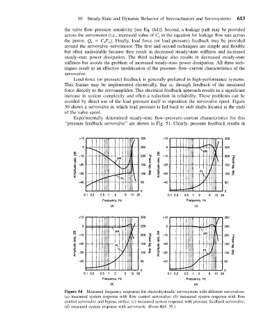
Figure 54 Measured frequency responses for electrohydraulic servosystem with different servovalves:
(a) measured system response with flow control servovalve; (b) measured system response with flow
control servovalve and bypass orifice; (c) measured system response with pressure feedback servovalve;
(d) measured system response with servovavle. (From Ref. 35.)