
Page 624 - Mechanical Engineers' Handbook (Volume 2)
P. 624
10 Steady-State and Dynamic Behavior of Servoactuators and Servosystems 615
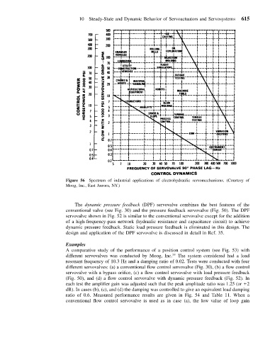
Figure 56 Spectrum of industrial applications of electrohydraulic servomechanisms. (Courtesy of
Moog, Inc., East Aurora, NY.)
The dynamic pressure feedback (DPF) servovalve combines the best features of the
conventional valve (see Fig. 30) and the pressure feedback servovalve (Fig. 50). The DPF
servovalve shown in Fig. 52 is similar to the conventional servovalve except for the addition
of a high-frequency-pass network (hydraulic resistance and capacitance circuit) to achieve
dynamic pressure feedback. Static load pressure feedback is eliminated in this design. The
design and application of the DPF servovalve is discussed in detail in Ref. 35.
Examples
A comparative study of the performance of a position control system (see Fig. 53) with
different servovalves was conducted by Moog, Inc. 35 The system considered had a load
resonant frequency of 10.3 Hz and a damping ratio of 0.02. Tests were conducted with four
different servovalves: (a) a conventional flow control servovalve (Fig. 30), (b) a flow control
servovalve with a bypass orifice, (c) a flow control servovalve with load pressure feedback
(Fig. 50), and (d) a flow control servovalve with dynamic pressure feedback (Fig. 52). In
each test the amplifier gain was adjusted such that the peak amplitude ratio was 1.25 (or 2
dB). In cases (b), (c), and (d) the damping was controlled to give an equivalent load damping
ratio of 0.6. Measured performance results are given in Fig. 54 and Table 11. When a
conventional flow control servovalve is used as in case (a), the low value of loop gain