
Page 625 - Mechanical Engineers' Handbook (Volume 2)
P. 625
616 Servoactuators for Closed-Loop Control
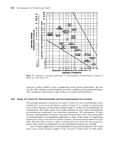
Figure 57 Spectrum of aerospace applications of electrohydraulic servomechanisms. (Courtesy of
Moog, Inc., East Aurora, NY.)
required to produce stability results in significantly poorer dynamic performance. But only
case (d), with a dynamic pressure feedback servovalve, combines good dynamic performance
with a significant improvement in static stiffness to external load disturbances.
10.6 Range of Control for Electrohydraulic and Electromechanical Servosystems
Two principal parameters characterize the range of control for most electrohydraulic servo-
36
mechanisms : power level and dynamic response. Figure 55 is a graph of control power
versus control dynamics showing three dominant ranges of control for electrohydraulic ser-
vomechanisms. The middle region of the graph represents the range where electrohydraulic
servomechanisms traditionally have dominated applications. Yet developments of high-
effeciency and high-speed-of-response rare earth servomotors have led to increased numbers
of electromechanical servomechanism applications in parts of this region. For applications
requiring low power levels and low dynamic response, electromechanical solutions are gen-
erally preferred. There remains a region involving high power level and high dynamic re-
sponse where neither electrohydraulic nor electromechanical solutions are available.
Areas of typical applications of electrohydraulic servosystems are plotted on the control
power versus control dynamics graphs of Figs. 56 and 57. Future needs for both electro-