
Page 623 - Mechanical Engineers' Handbook (Volume 2)
P. 623
614 Servoactuators for Closed-Loop Control
Table 11 Comparative Performance of Various Electrohydraulic Position Servomechanisms
Bandwidth ( 2 dB), 90 Phase Lag, Static Load Stiffness,
Servo Configuration Hz Hz lb/in.
Flow control servovalve 0.15 0.37 9,000
Flow control servovalve with bypass 8.8 5 5,100
orifice
Flow control servovalve with pressure 8.8 5 2,500
feedback
DPF servovalve 9.2 5 60,000
Source: From Ref. 35.
a reshaping of the characteristics from those of the conventional servovalve (see Fig. 34). In
particular, the flow-pressure sensitivity [see Eq. (64)] or slope of the characteristic curves
(C ) is increased in the vicinity of I 0, P 0 when pressure feedback is used. But an
1
m
increase in this slope results in an increase in K and therefore the load sensitivity [see Eq.
2
(114)].
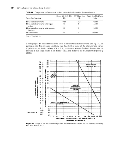
Figure 55 Range of control for electrohydraulic servomechanisms. (From Ref. 36. Courtesy of Moog,
Inc., East Aurora, NY.)