
Page 642 - Mechanical Engineers' Handbook (Volume 2)
P. 642
3 Frequency Compensation to Improve Overall Performance 633
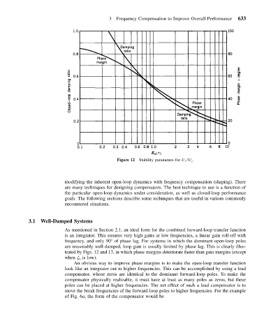
Figure 12 Stability parameters for U 1 /U c .
modifying the inherent open-loop dynamics with frequency compensation (shaping). There
are many techniques for designing compensators. The best technique to use is a function of
the particular open-loop dynamics under consideration, as well as closed-loop performance
goals. The following sections describe some techniques that are useful in various commonly
encountered situations.
3.1 Well-Damped Systems
As mentioned in Section 2.1, an ideal form for the combined forward-loop transfer function
is an integrator. This ensures very high gains at low frequencies, a linear gain roll-off with
frequency, and only 90 of phase lag. For systems in which the dominant open-loop poles
are reasonably well damped, loop gain is usually limited by phase lag. This is clearly illus-
trated by Figs. 12 and 13, in which phase margins deteriorate faster than gain margins (except
when is low).
2
An obvious way to improve phase margins is to make the open-loop transfer function
look like an integrator out to higher frequencies. This can be accomplished by using a lead
compensator, whose zeros are identical to the dominant forward-loop poles. To make the
compensator physically realizable, it must have at least as many poles as zeros, but these
poles can be placed at higher frequencies. The net effect of such a lead compensator is to
move the break frequencies of the forward-loop poles to higher frequencies. For the example
of Fig. 6a, the form of the compensator would be