
Page 645 - Mechanical Engineers' Handbook (Volume 2)
P. 645
636 Controller Design
s 1
G c3 z3 (18)
s
and
2
2
s / (2 / )s 1
G z4 z4 z4 (19)
c4
s( s 1)
p4
Because of the noise-attenuating effect of the electronic integrator, 1/ p4 can often be set a
factor of 10 greater than . As previously discussed, the ratio of / in Eq. (17) is
z4
cp
cz
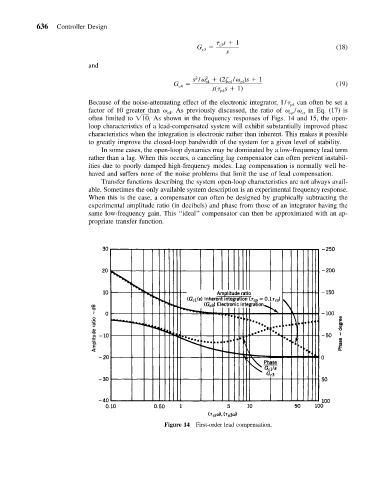
often limited to 10. As shown in the frequency responses of Figs. 14 and 15, the open-
loop characteristics of a lead-compensated system will exhibit substantially improved phase
characteristics when the integration is electronic rather than inherent. This makes it possible
to greatly improve the closed-loop bandwidth of the system for a given level of stability.
In some cases, the open-loop dynamics may be dominated by a low-frequency lead term
rather than a lag. When this occurs, a canceling lag compensator can often prevent instabil-
ities due to poorly damped high-frequency modes. Lag compensation is normally well be-
haved and suffers none of the noise problems that limit the use of lead compensation.
Transfer functions describing the system open-loop characteristics are not always avail-
able. Sometimes the only available system description is an experimental frequency response.
When this is the case, a compensator can often be designed by graphically subtracting the
experimental amplitude ratio (in decibels) and phase from those of an integrator having the
same low-frequency gain. This ‘‘ideal’’ compensator can then be approximated with an ap-
propriate transfer function.
Figure 14 First-order lead compensation.