
Page 646 - Mechanical Engineers' Handbook (Volume 2)
P. 646
3 Frequency Compensation to Improve Overall Performance 637
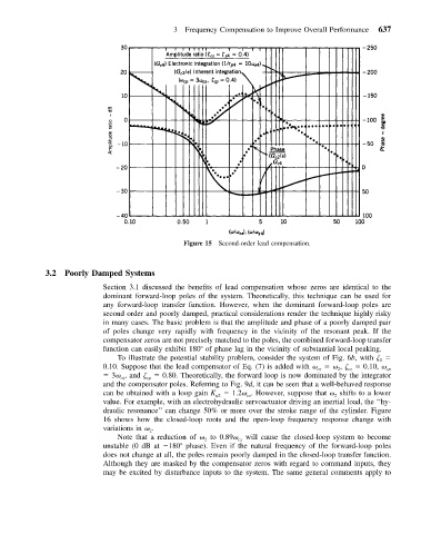
Figure 15 Second-order lead compensation.
3.2 Poorly Damped Systems
Section 3.1 discussed the benefits of lead compensation whose zeros are identical to the
dominant forward-loop poles of the system. Theoretically, this technique can be used for
any forward-loop transfer function. However, when the dominant forward-loop poles are
second order and poorly damped, practical considerations render the technique highly risky
in many cases. The basic problem is that the amplitude and phase of a poorly damped pair
of poles change very rapidly with frequency in the vicinity of the resonant peak. If the
compensator zeros are not precisely matched to the poles, the combined forward-loop transfer
function can easily exhibit 180 of phase lag in the vicinity of substantial local peaking.
To illustrate the potential stability problem, consider the system of Fig. 6b, with
2
0.10. Suppose that the lead compensator of Eq. (7) is added with , 0.10, cp
cz
2
cz
3 , and cp 0.80. Theoretically, the forward loop is now dominated by the integrator
cz
and the compensator poles. Referring to Fig. 9d, it can be seen that a well-behaved response
can be obtained with a loop gain K u2 1.2 . However, suppose that shifts to a lower
cz
2
value. For example, with an electrohydraulic servoactuator driving an inertial load, the ‘‘hy-
draulic resonance’’ can change 50% or more over the stroke range of the cylinder. Figure
16 shows how the closed-loop roots and the open-loop frequency response change with
variations in .
2
Note that a reduction of to 0.89 will cause the closed-loop system to become
2
cz
unstable (0 dB at 180 phase). Even if the natural frequency of the forward-loop poles
does not change at all, the poles remain poorly damped in the closed-loop transfer function.
Although they are masked by the compensator zeros with regard to command inputs, they
may be excited by disturbance inputs to the system. The same general comments apply to